General
The Installation of URCap must be completed before the following.
Network Setup
To establish the network connection between the robot and the SpinBridge, you must set up the network on the robot. This is done by entering the network details on the System/Network tab in the Settings menu. Remember to setup the network on the SpinBridge via the SpinInterface as well. See the SpinBridge documentation for details.
The robot and the SpinBridge can be connected in different configurations.
The robot and the SpinBridge are both connected to a network switch via the upper port 1. Ext. network on the SpinBridge.
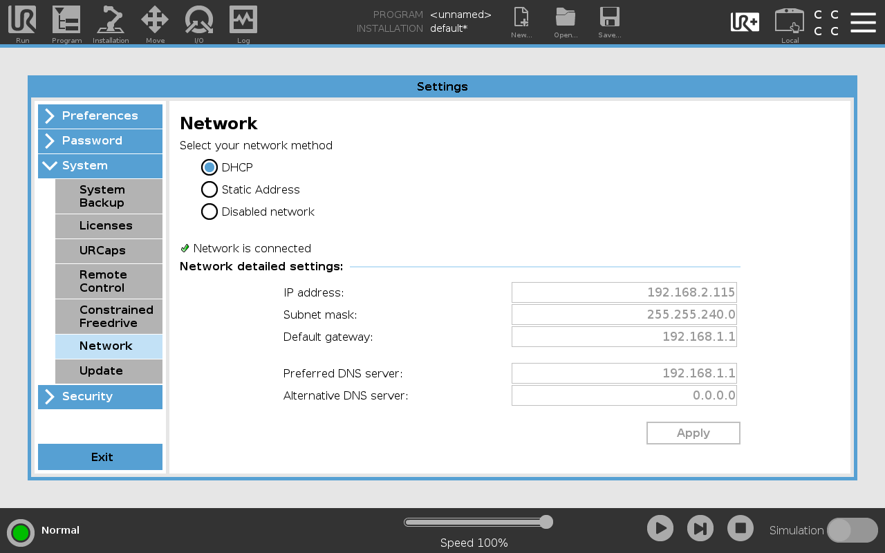
If the network has DHCP enabled, you can select DHCP on the Network tab. Then the robot will automatically get an IP address.
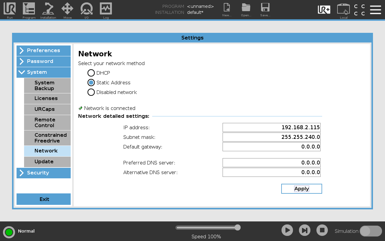
If the network does not have DHCP, you must you must select Static Address on the Network tab and at least enter an IP address and Subnet mask manually.
The robot and the SpinBridge are connected directly via the lower port 2. Robot.
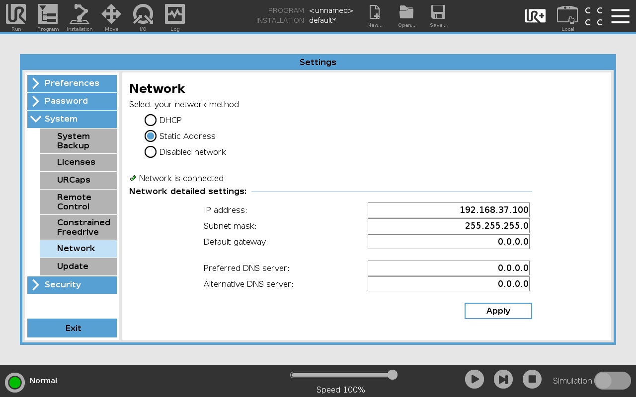
Then you must select Static Address on the Network tab and enter the IP address: 192.168.37.100 [1] and Subnet mask: 255.255.255.0 manually.
Remember to press Apply to save the settings.
Enable RTDE
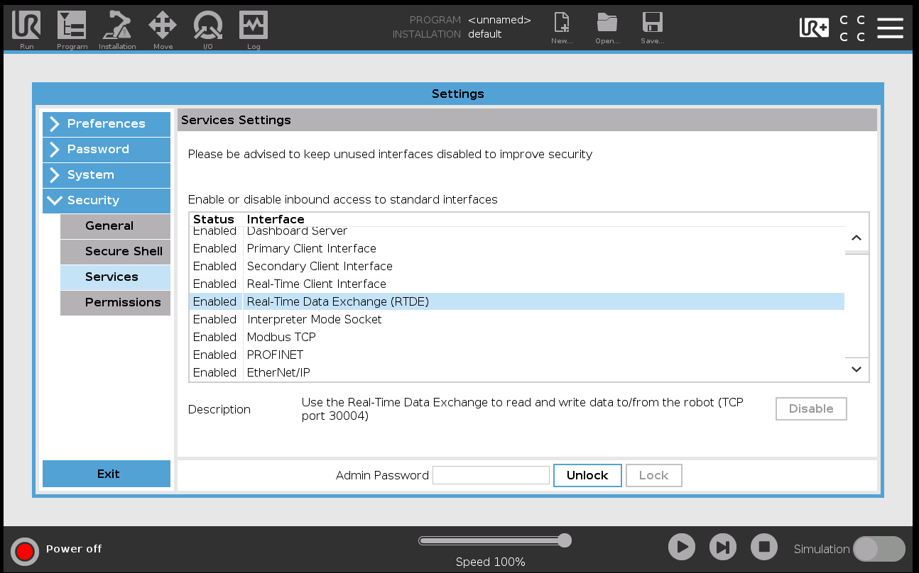
The SpinBridge uses RTDE (Real Time Data Exchange) to communicate with the robot. This must be enabled on the robot.
Tool Center Point
The TCP must be setup by selecting the correct tool from the dropdown menu on the Installation/General/TCP tab. The TCP is saved in the installation file.
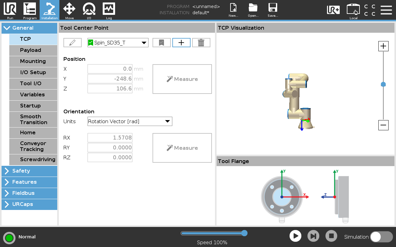
TCP tab.
Note
You can alter the TCP values if you have a customized TCP, e.g. if the tool is mounted on a 3’rd party tool changer. This also applies if the screw bit length is changed from the default value of 50 mm.
Payload
The payload must be setup by selecting the correct tool from the dropdown menu on the Installation/General/Payload tab. The payload is saved in the installation file.
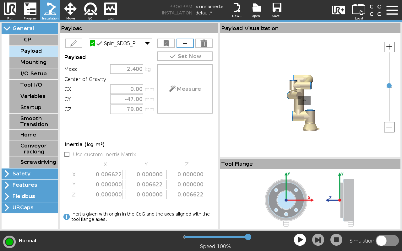
Payload tab.
I/O Setup
To enable Freedrive and Front button on the tool please follow these instructions.
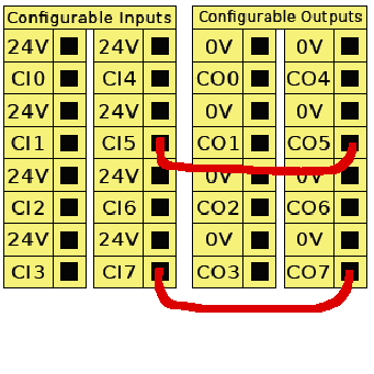
The configurable I/O connector in UR Control Box.
Power off robot.
Open the UR Control Box.
Insert jump wire from CI5 to CO5 and CI7 to CO7 as shown in the figure to the right.
Power on robot.
Map the configurable input CI7 to freedrive and CI5 to any action you desire. This is done on the Installation/General/I/O Setup tab as shown in the figure below.
The I/O setup is saved in the installation file.
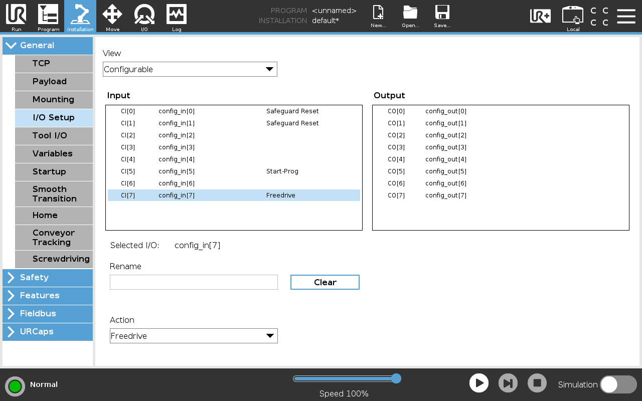
I/O Setup tab.
Screwdriving
You should NOT setup up anything on the Installation/General/Screwdriving tab. This URCap does not rely on the UR screwdriving functionality.